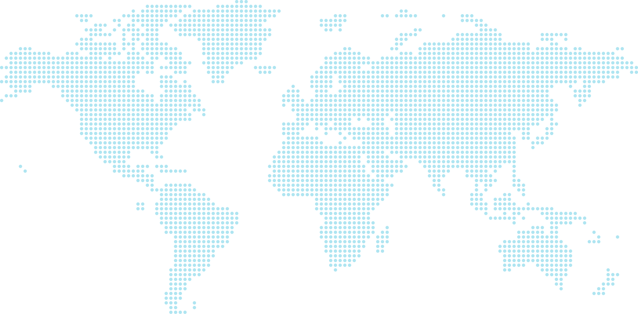

With more than 15,000 customers worldwide, MARECHAL ELECTRIC is a French group with an international presence able to meet the needs of all industries.
Our Expertises
Our ranges
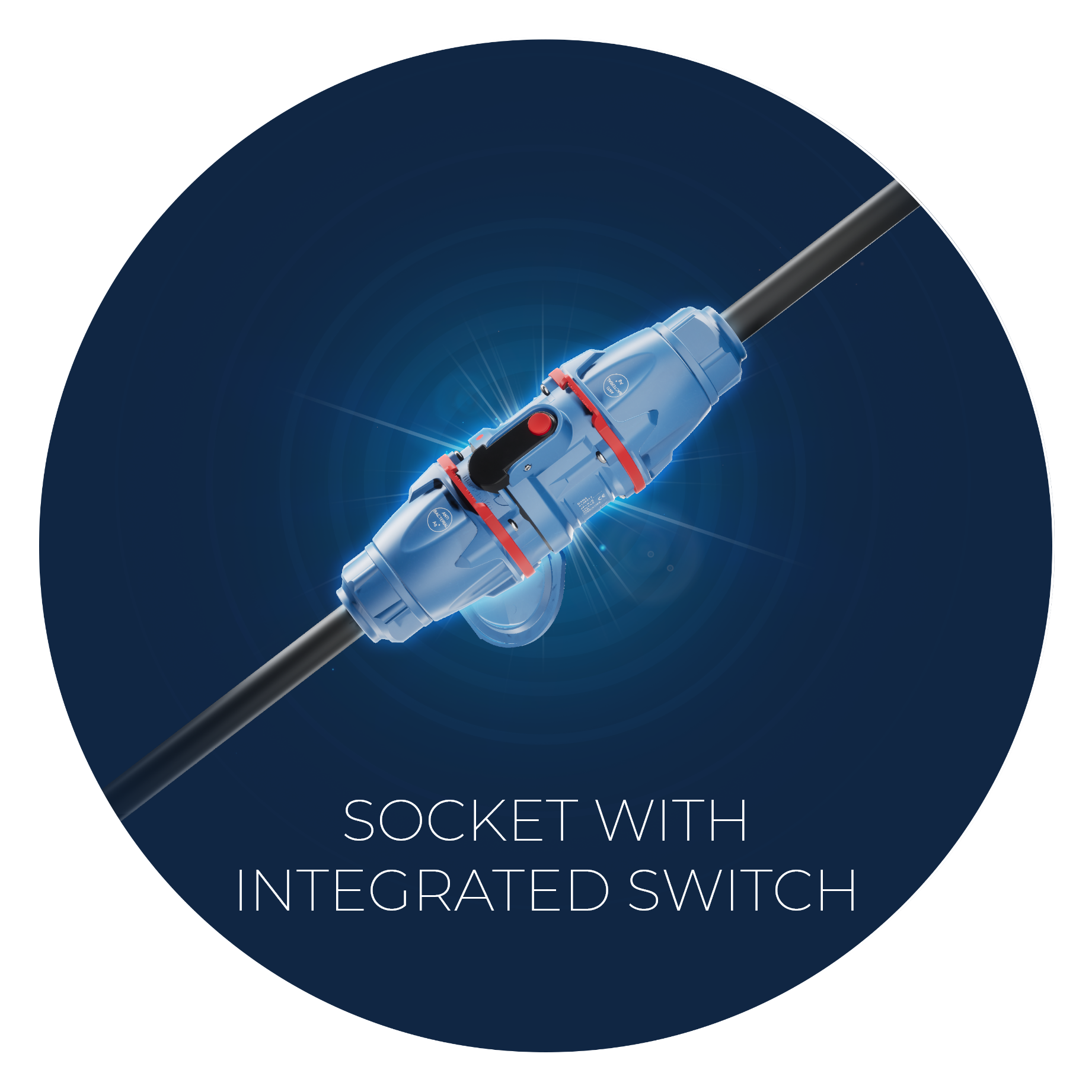
SAFE AREA
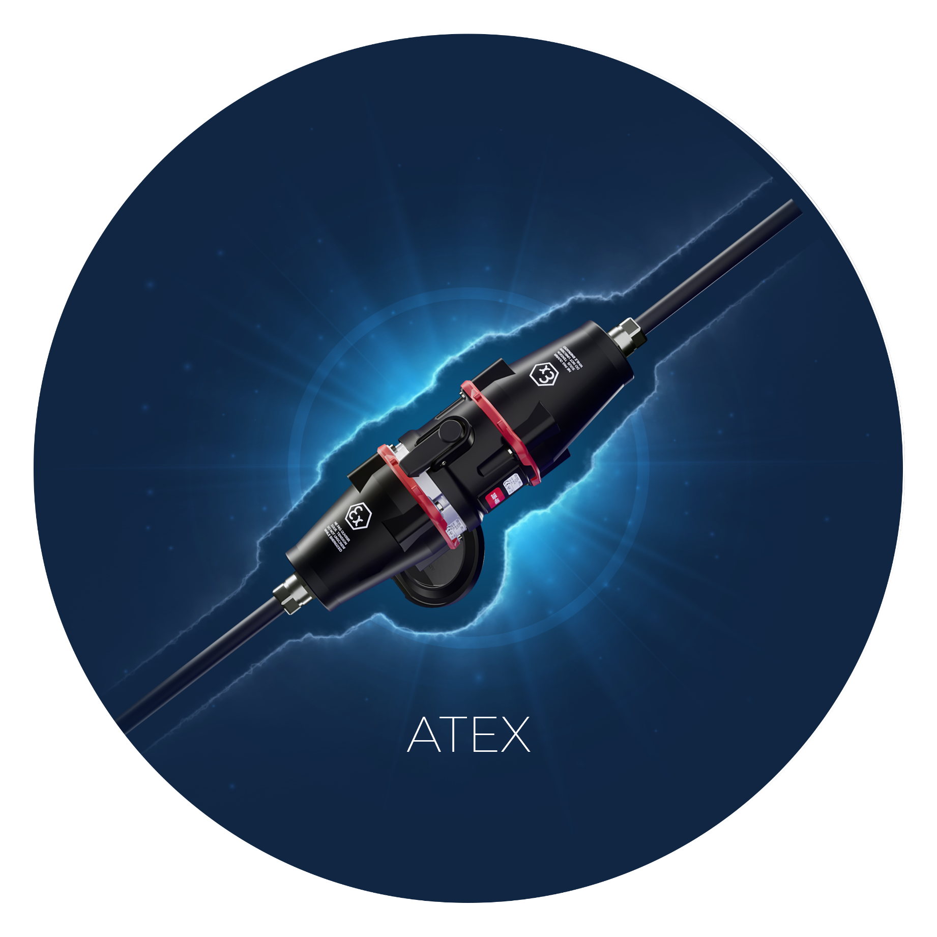
ATEX

-
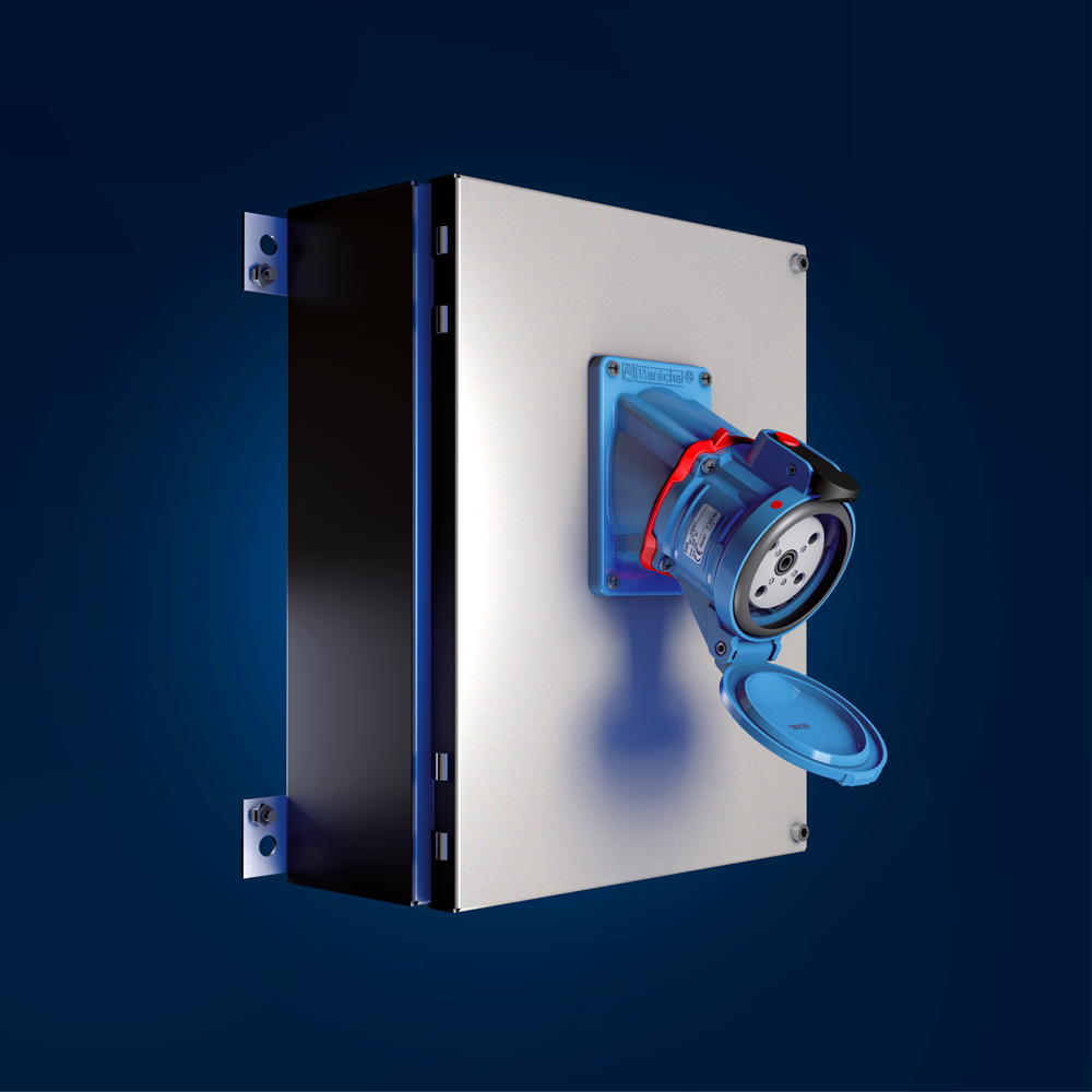
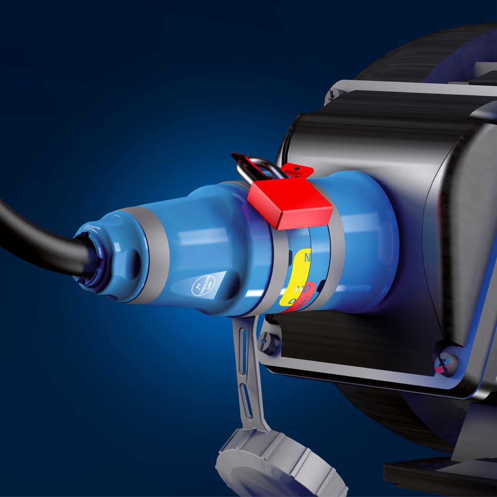
Safe Area
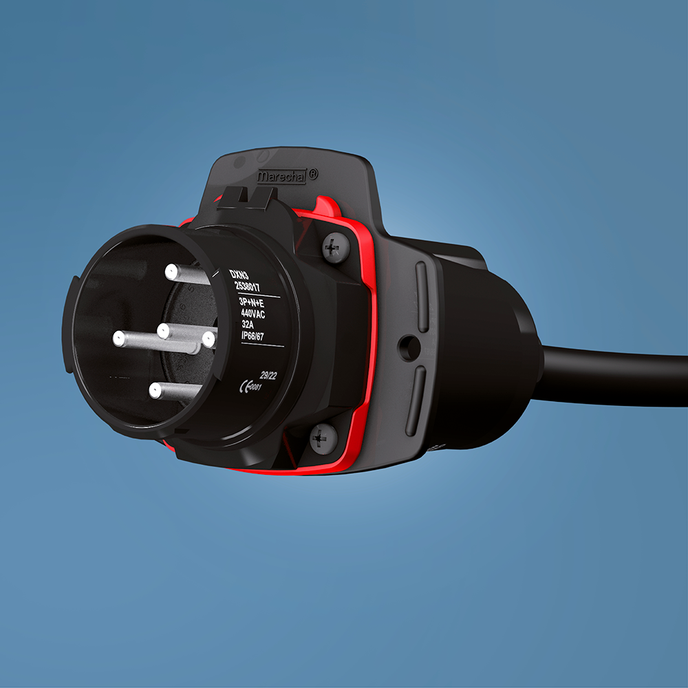
high-current Ex connectors
from 16 A to 1250 A -
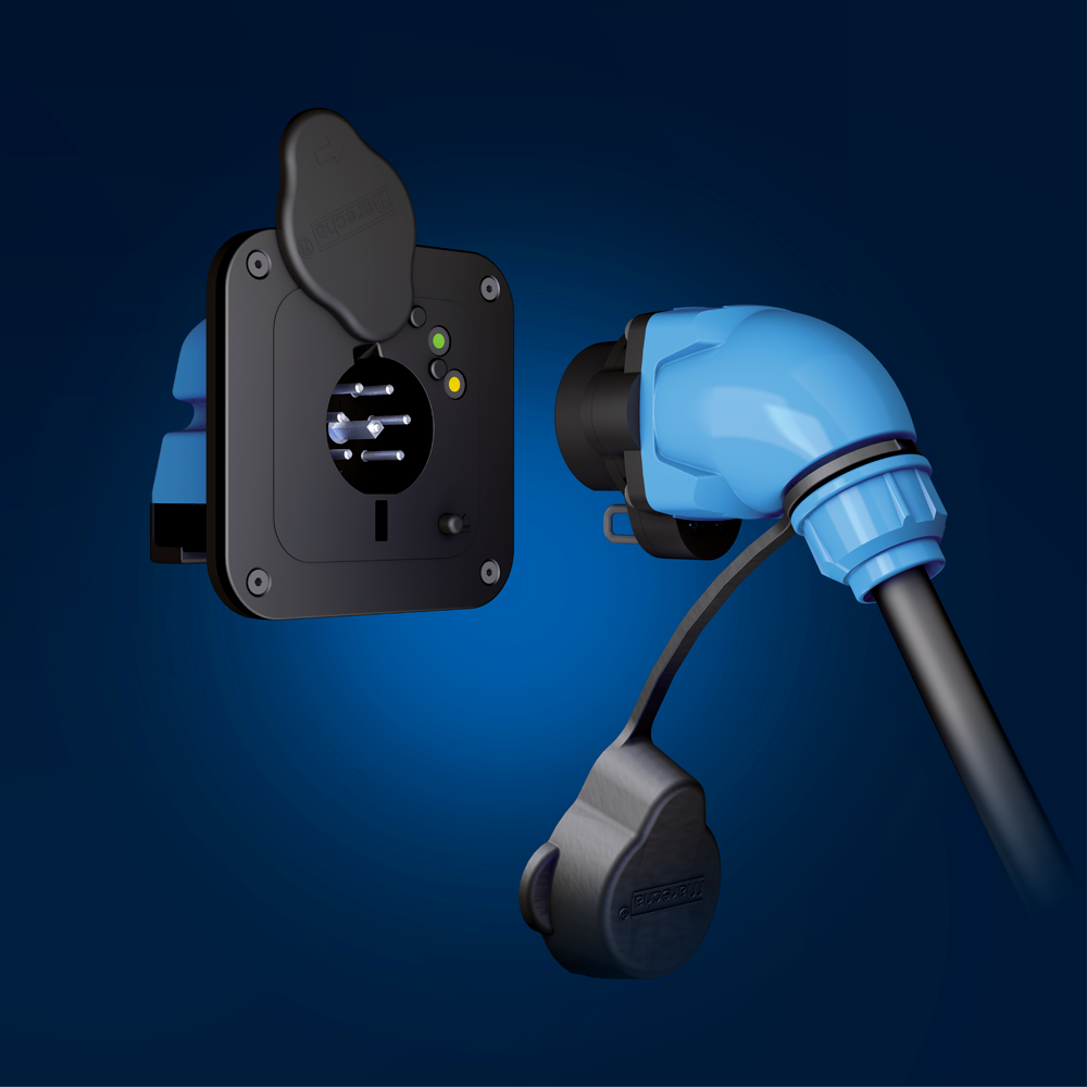
Safe Area
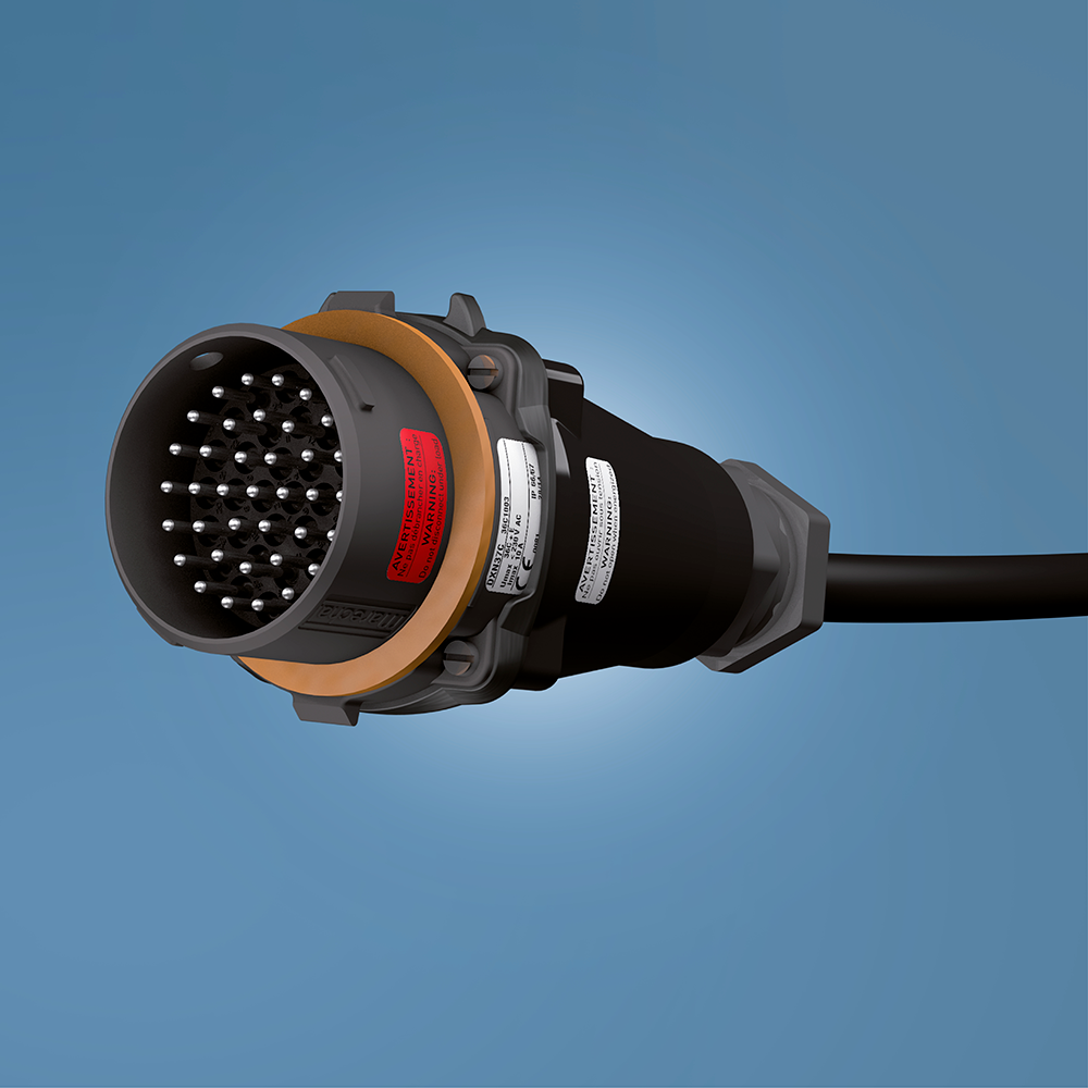
Low current Ex connectors
from 12 to 37 contacts -
Safe Area
Junction and distribution boxes, extension cords and reels
-
Safe Area
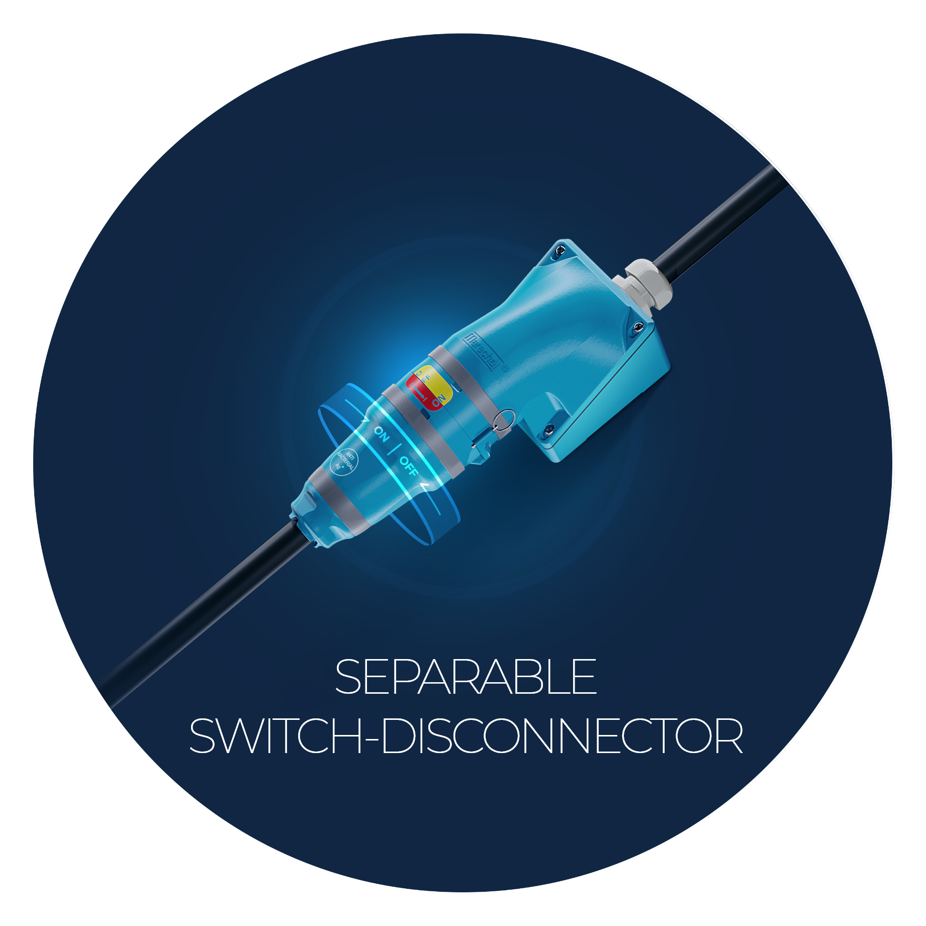
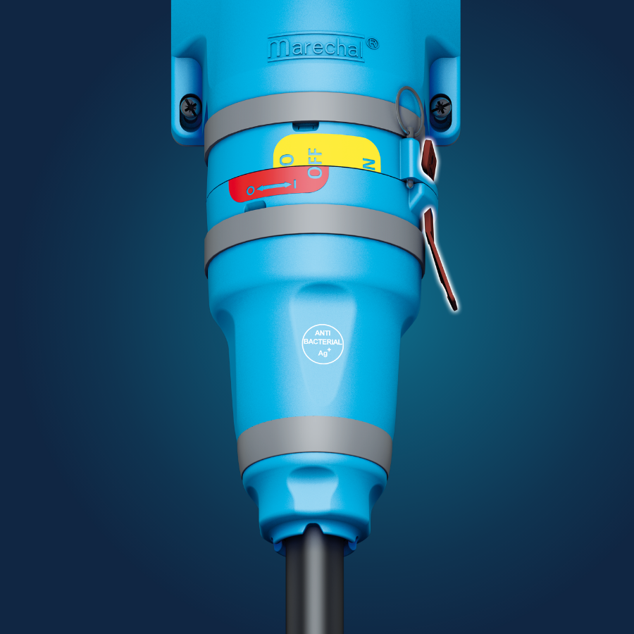
18.5 kW switch-disconnectors
-
Safe Area
Mobile applications
-
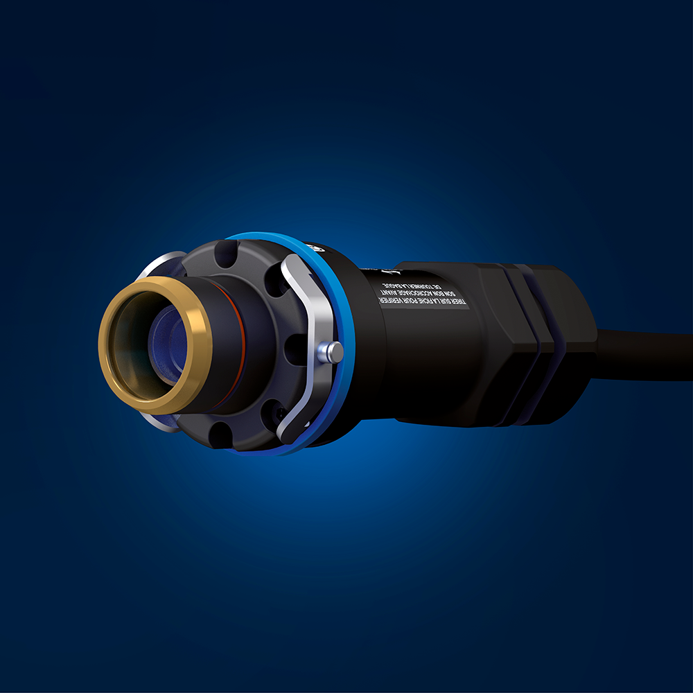
Safe Area
Unipolar connectors
-
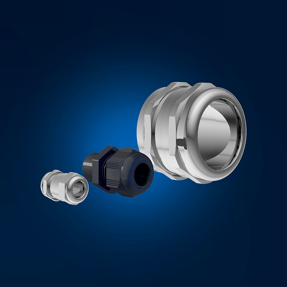
Safe Area
Cable glands
-
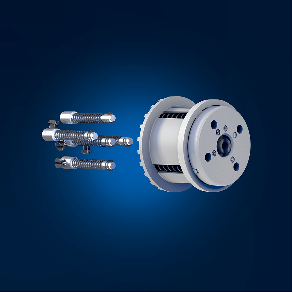
Safe Area
Spare parts
-
Atex
Custom solutions
-
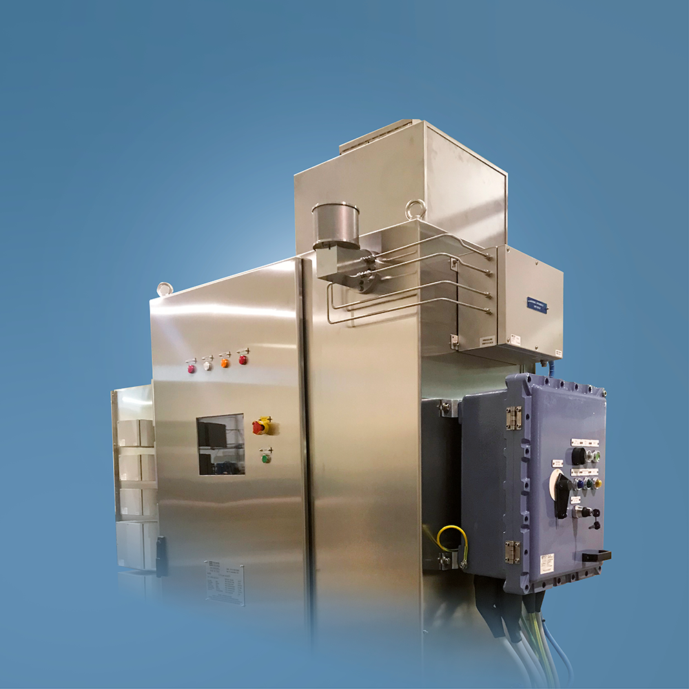
Atex
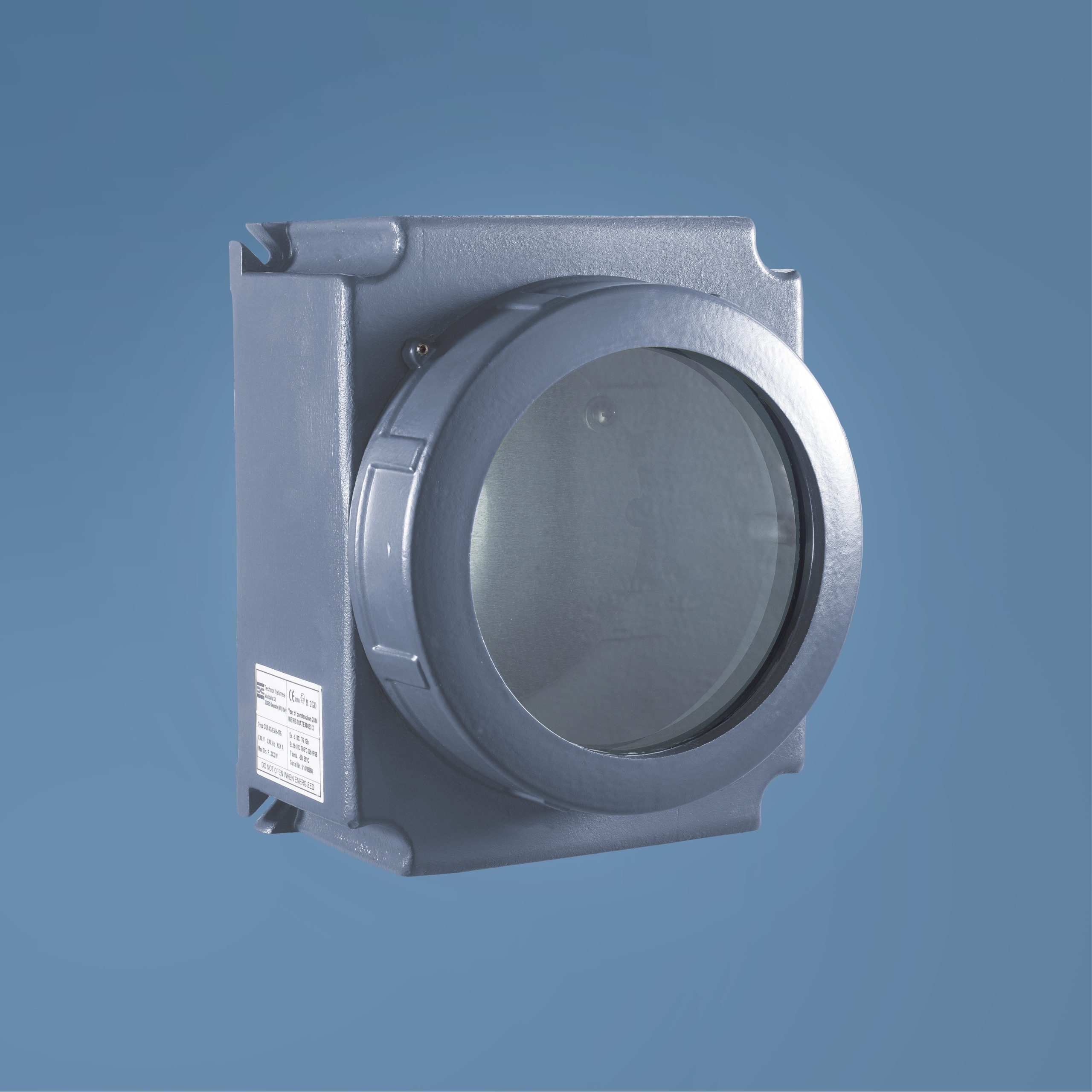
Explosionproof enclosures
-
Atex
Explosionproof enclosures
-
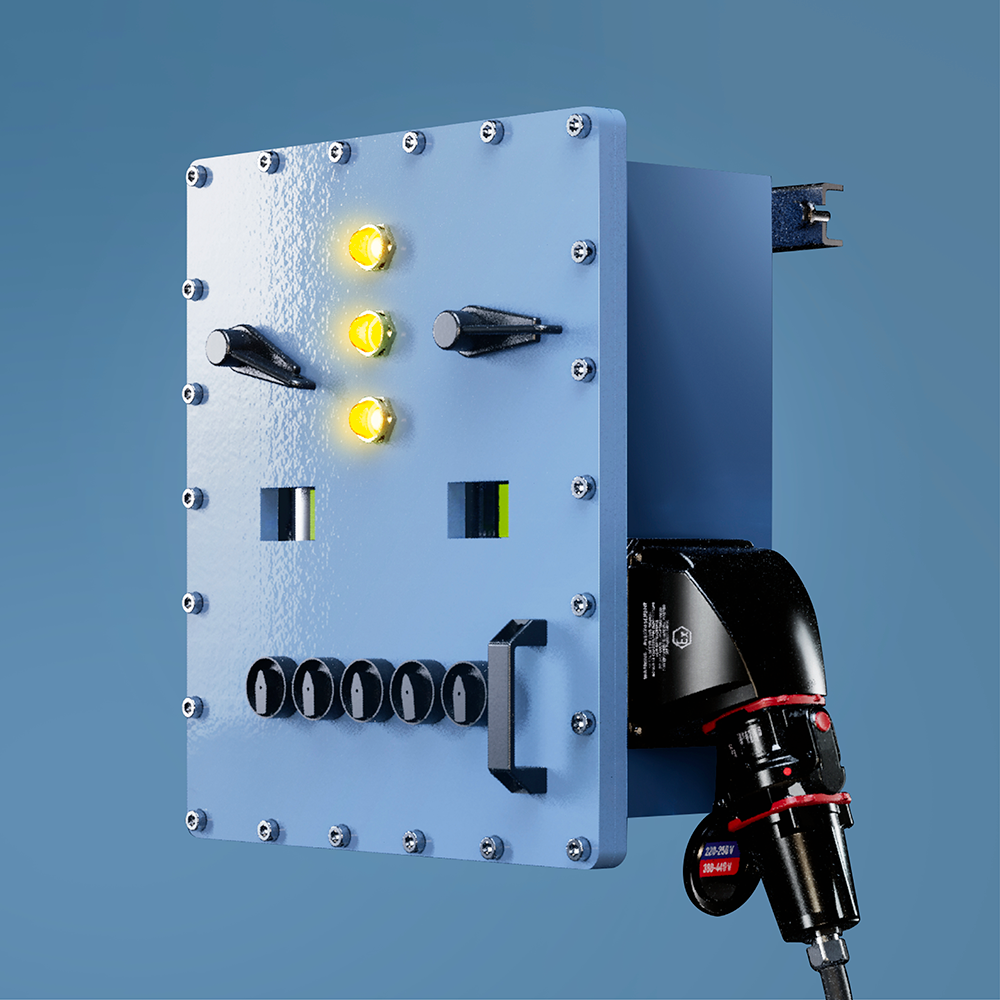
Atex
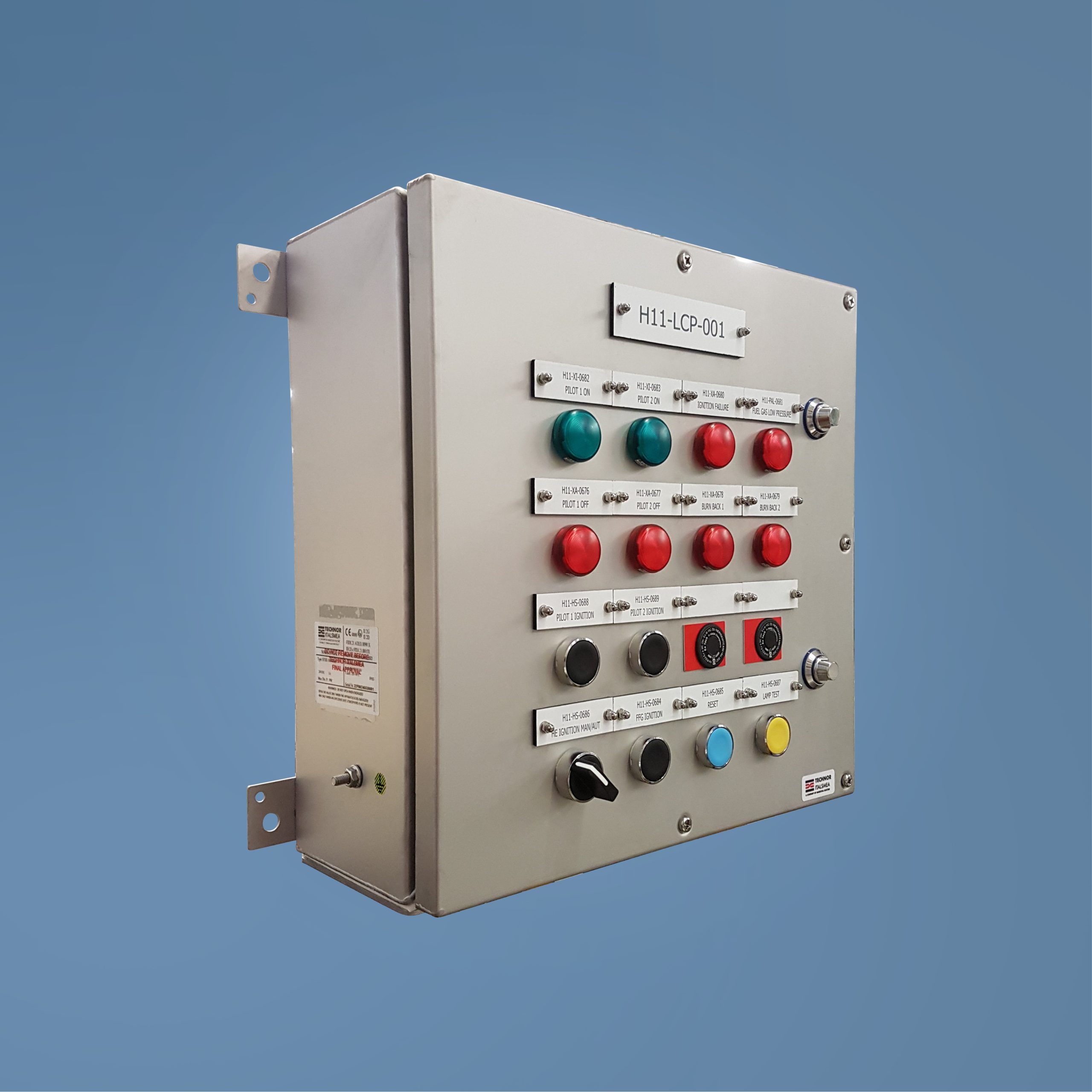
Fitted increased safety enclosures
-
Atex
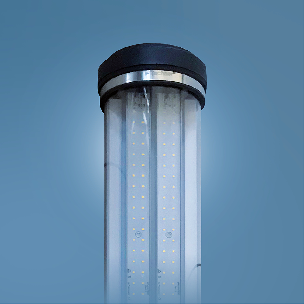
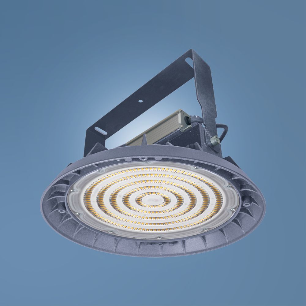
Lighting zone 1-21
-
Atex
Lighting zone 2-22
-
Atex
high-current Ex connectors
from 5 A to 680 A -
Atex
Low current Ex connectors
from 12 to 37 contacts
PRODUCT CONFIGURATOR
CONFIGURE YOUR PLUG SOCKET-OUTLET IN 3 STEPS
- 1ENTER YOUR TECHNICAL DATA
- 2CHOOSE YOUR OPTIONS
- 3OBTAIN YOUR REFERENCE
MARECHAL ELECTRIC
An international group
- 70 years
of expertise - UNIQUE
know-how - 9
SUBSIDIARIES - Made in France
since 1952
Contact your sales representative
CONTACT
Have a look
Explore our product catalogues and find what you need.
Environment
Energy efficiency
FIND OUT MORE
 Reduce your electricity consumption
 Reduce your maintenance costs: availability of spare parts.
 Reduce your carbon footprint
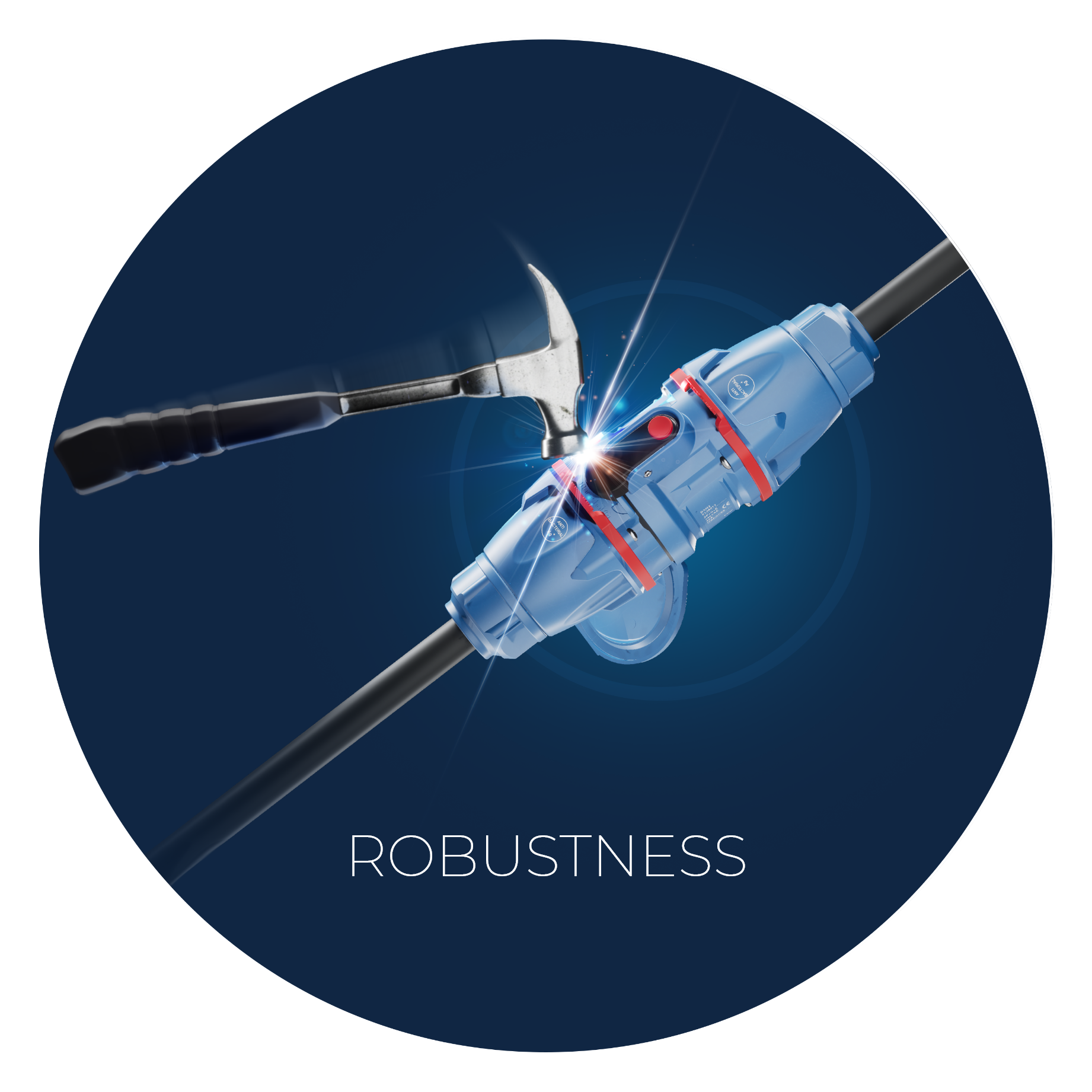
 Long-lasting equipment thanks to high-performance, resistant materials
Our News

State-of-the-art technology